Sep 28, 2012 , by
Public Summary Month 9/2012
4th Public Report
In tests with a robot system utilizing a phantom simulator that imitates roughly the situation in the OP scene when holding retractors we could identify that it’s beneficial to mount the robot in a higher position. This way it can reach the workspace approaching from above and the robot will less likely get to edge of configuration space (above/below). Further mounting the robot side wards to the column instead should prevent the robot to get into singularities that occurred often in the tests due to alignment of two rotational axes.
The gripper was redesigned to be functional again if robot is mounted differently. In summary these changes reduce the risks of the robot to collide with patient staff. The new setup can be seen in Figure 1.
Figure 1: CAD design of the column for the newly arranged retractor holding robot utilizing the new gripper design.
We started testing markers with chess patterns to track the 6D pose of the tools. These markers were bundled in a cube so they can be seen from every direction and mitigate the problem of partial occlusions. However, a camera setup different than what was previously planned might be needed, due to the lack of precision when the markers are far away from the camera.
The positioning of the eye-to-hand camera relative to the rest of the system has been specified.
To handle the risks brought along with utilizing a robot system medical and technical experts met and discussed what risks have to be handled and how this can be done. A list of system components was created, together with associated safety standards.
Jul 26, 2012 , by
Public Summary Month 7/2012
3rd Public Report
We recieved the robot controller and started working on the control algorithm successfully.
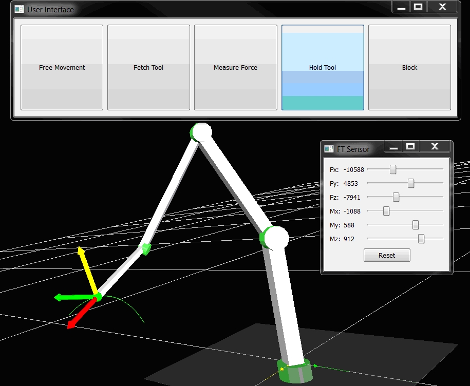
The communication interface between Control PC and Robot Controller was implemented. The control was programmed to command the robot between four different working modes. Since we don’t have all the hardware yet, all tests were conducted in simulation mode (Figure 1).

Figure 1 – The simulated robot holding and rotating the (imaginary) tool around the bone.
We acquired the camera and tested it successfully.
The gripper for holding surgical bone levers was redesigned to be shorter in length and allow to couple medical retractors from the front side.
To handle the risks brought along with utilizing a robot system medical and technical experts met and discussed what risks have to be handled and how this can be done.
May 25, 2012 , by
Public Summary Month 5/2012
2nd Public Report
In tests with the existent assistance robot system and a mechanical simulator developed in the previous “AssRob Project” the alignment of the robot was examined. It was found that the workspace gets increasingly reduced as function of the attached end-effectors length. This result will be considered when optimizing the coupling devices. A further result of the tests was that the flow of forces of the current gripper design results in discharging the less powerful joints of the robot, as planed.
For the tracking of medical retractor by the robot system we decided to use a RGB-D sensor for the pose estimation of the tools, mounted on a fixed location. The tracking method will be based on shape recognition and for that we will attach a rigid-body to the tool.
Mar 30, 2012 , by
Public Summary Month 3/2012
1st Public Report
The setup of the modular robot system has been distinguished in cooperation with the robot manufacturer. To validate that the robot can fulfill the planed task to hold surgical bone levers a model of the experiment setup was created.
Further, suitable Force-Torque-Sensors and the power supplies were selected. A robot control was selected and the software setup of the control-PC has been started. It was discussed what cameras and markers can be used. Mounting the robot to a column has been prepared.


