
Aug 27, 2012 , by
Public Summary Month 7/2012
Taks 7: System testing
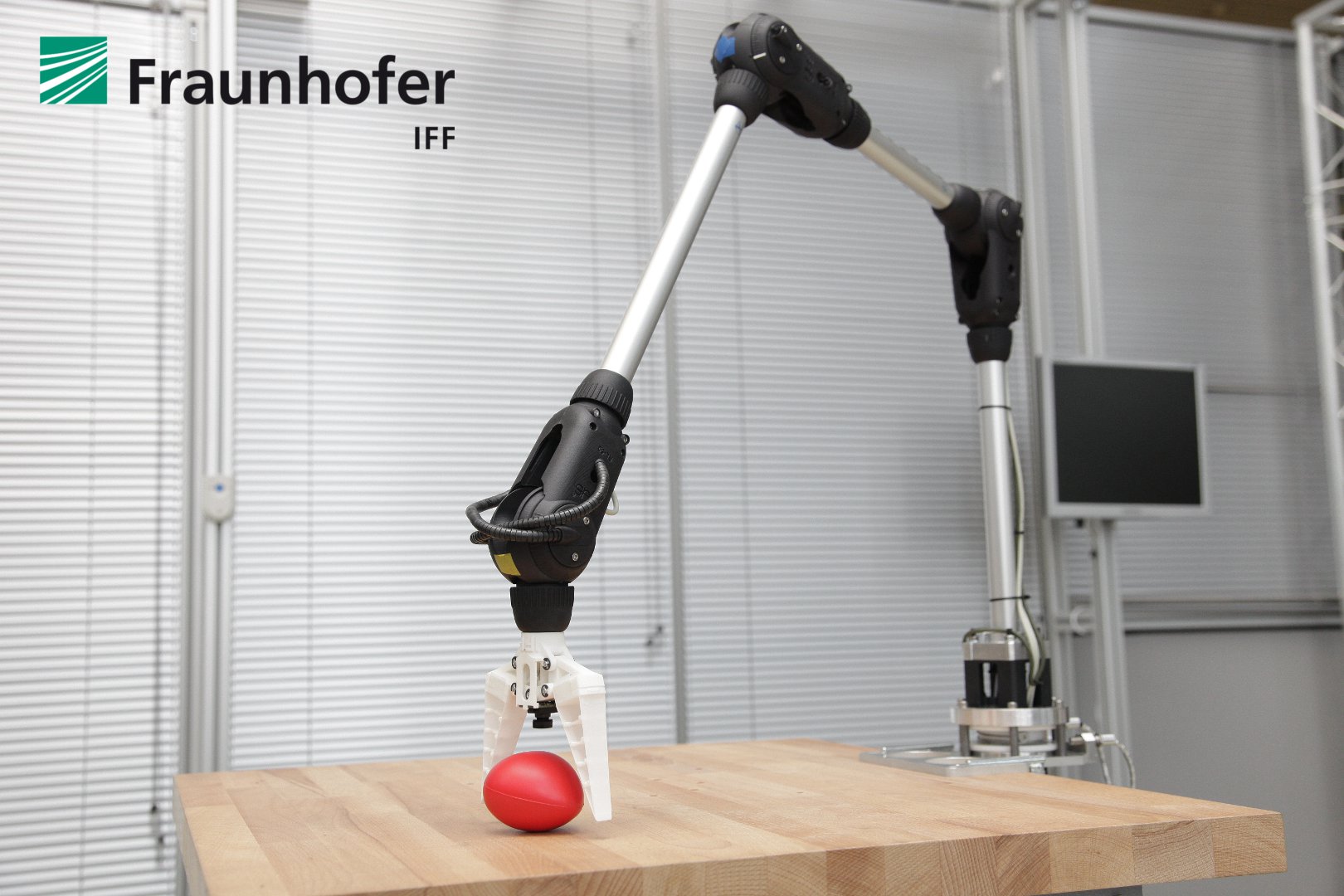
Within our last experiment steps we evaluated and optimized the entire robot system. In the first step we examined the object recognition and position estimation of Camera A. The camera configuration and image processing were improved until the derivation did not left a range of ±50mm. In the next step we examined the positioning of the gripper. The system was improved until the deviation may amount to only ±5mm, so that the pick procedure can be done successfully.
After the evaluation of the cameras and image processing, we optimized the position control of the robot to improve the repeatability. After optimization we arranged the scenario as it was introduced in the proposal with a set of three different tagged cubes. In several repetitions we diversified the position of the cube in the range of Camera A, in order to determine the reliability of the system. The experiment was considered as final, as soon as the system was able to grip tagged objects in its vision range and deposit these objects in a defined target position.
Furthermore we arranged a second scenario in that small cylinders with a through-hole were threaded onto a needle. Here, the dimension of a single cylinder was 10x5mm (height by diameter) and the mentioned through-hole had a diameter of 3mm. The robot was able to thread all cylinders onto the needle, which verified a repeatability of ±1.5mm.
Taks 8: Dissemination
In the last two experiment month, the most important dissemination activities were:
- The Multimeda Report was created and is now available here: http://www.youtube.com/watch?v=o94NYrFNRmo
- We preparing the last presentation about our ALEXA experiment that will be given at the IROS 2012 during the ECHORD workshop. The workshop schedule is available here: http://echord.info/wikis/website/iros-2012-workshop
Photographs of the ALEXA robotic arm
.jpg.html)
.jpg.html)
.jpg.html)
.jpg.html)
.jpg.html)
.jpg.html)
Feb 6, 2012 , by
Public Summary Month 1/2012
Task 4
We finalized the main control of the ALEXA robot. Finally, it has the following features:
- Functionalities to compute paths with minimal joint loads (PTP motions) and in optimum time (LIN motions)
- Generator that computes position and velocity trajectories in the joint space
- Decentralized position controllers that combine motor and joint states to reduce the elastic effects of the actuation ropes
Furthermore, we optimized the position controllers to improve the motion capabilities of the robotic arm. In parallel, we developed a new feedforward controller that adjusts the rope tension of the respective actuated joint to an operating value.
Task 5
In early December of 2011, we began to implement the image processing modules for marker and object recognition as well as visual servoing functionalities. The implementation is currently in progress. In the following month, we plan to finalize the implementation. Afterwards, we will commission the mentioned modules and run some test to evaluate them.
Task 6
In December 2011, we constructed a mounting system to attach common cable channels and the multi camera system on the stiff links of the robotic arm. Further, we produced all mounting components and installed them on the robotic arm. Currently, we renew the pull-through of all sensor and camera cables as well as its plugs. In the next step, we will commission and calibrate the camera system.
Dec 7, 2011 , by
Public Summary Month 11b/2011
Task 3
During the first all-over motion test, we find out that the load torque of some drive motors reached a critical value. The reason here was the high friction in the Bowden cables and in the rope lead-throughs. To reduce the friction influence, we assembled Teflon coats over the related ropes for better frictional properties. After that we ran a new all-over motion test. This time, the loads of the drives were obviously lower.
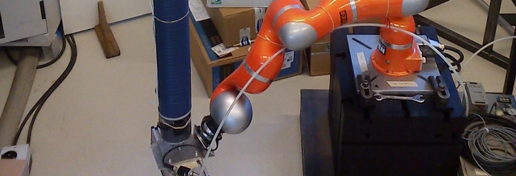
Now, the entire robotic arm and its compact drive unit is completley built-up and finalized. The ALEXA robotic system is shown by Figure 1 to Figure 4.
![]()
Figure 1: ALEXA robotic arm
![]()
Figure 2: Compact drive unit
![]()
Figure 3: Detailed view of the rope actuating drives manufactured by Schunk
![]()
Figure 4: Wrist joint
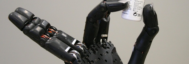
Further, we constructed a lightweight gripper that can be actuated by a rope. The gripper is made out of Polyamid 12 and was produced in Rapid Prototyping techniques. Furthermore, we used compliant fingers with FinRay design manufactured by Festo. A socket for the camera was also integrated.
Task 4
The implementation of the main control system is almost finished. The main control system includes a software system that controls the drive motors, plans optimized trajectories, acquires all sensor data and avails image processing interfaces. Now, we debugging all software parts and searching for optimization potentials.
Task 5
We began to prepare all existing software modules for image processing and object recognition to link with the interfaces of the main control software. After debugging and optimizing the main control software is finished we will implement the visual servo control algorithms.
Aug 8, 2011 , by
Public Summary Month 7/2011
Progress of the ALEXA experiment
Task 1 – Technical concept
Concept of the ALEXA Robotic Arm In the first stage, the joint configuration and the links length of the 5-DOF ALEXA robotic arm were determined by optimizing the workspace. Here, all constraints (angular range of the joints, etc.) and conditions (load-case, etc.) were take into account.
Separating the robotic arm from drive system is a key feature of the ALEXA robot system, and should allow for good transportability. A tensing mechanism was designed that allows for the Bowden cables to be detached from the drive modules.
Concept of the Camera System and Visual Servoing The camera system for visually guiding the manipulator consists of two cameras: Camera A is mounted at the first link of the robotic arm (to detect relevant objects within the working area) and Camera B is mounted next the gripper (to pose the gripper). Since the ALEXA experiment is not concerned with object recognition, we will use markers to detect relevant objects.
Task 2 – Derivation of direct, indirect, and differential kinematics
Determination of kinematics The kinematic model of the ALEXA robotic arm consists of the solution of the direct, inverse, and differential kinematics. All solutions were determined in closed-form. Further, the equation of motion of the robotic arm was determined by following the Euler-Newton formulation.
Development of trajectories generator An algorithm for planning torque optimized paths and computing trajectories is still in progress.
Task 3 – Construction of the robot system
Construction of a prototype The actuation of one cable-driven Robolink joint is currently being tested with an experimental setup whereby the Bowden cables are long and laid out in an unrestricted manner. Furthermore, a mechanism to detach and tense the Bowden cables was built-up as well.
Construction of the robotic arm To extend the workspace of the ALEXA robotic arm, our project partner Igus has modified its standard Robolink joint and the transits of the actuation ropes. Finally Igus will build-up the whole robotic arm by the beginning of August.
Construction of the compact drive system The construction of the compact drive system is in an early state. We have begun to design the drive bearings and the detachable tensing mechanism.