
Oct 14, 2011 , by
Public Summary Month 9/2011
The Fraunhofer IFF continued the work on Task 2 “Realisation of passive kinematics” and began working on task 3 “Revaluation of path planning”. The experiment will probably reach milestone M1 “realisation of passive kinematics” at the end of November also with providing the Deliverable DHyropa2 “Passive kinematics prototype”.
The flexible arms have been modified and reassembled to prepare the scenario validation in task 5 ”Setup of test arrangement”. The initial tension of the arms was adjusted to the intended handling weights and the hydraulic system (for locking and unlocking the arms) was upgraded to the required pressure, flow rates and strokes. The mounting on the robot cell will be the next step.
Based on the classification of the use cases the manipulating of 3D tubes will be selected to demonstrate the properties of the flexible robot system. Therefore the number of joints must be matching to the desired handling tasks. For the grasping of different 3D formed tubes the arms will be mounted directly at the clamping table. The robot will achieve the reconfiguration of the arms and the transport of the tubes. The task of the flexible arms is to fix the tubes in a defined position at the table for executing different manufacturing steps such as cutting/trimming, connecting, and marking/labelling with the tubes. Such tubes are typically used in the automotive industry for the piping of ventilation and air conditioning or braking and steering circuits. Future possible uses are the production and assembling of 3D tubes for connecting of fuel cells with peripherical devices.
Aug 19, 2011 , by
Public Summary Month 7/2011
Project objectives
The experiment HYROPA demonstrates the possibility to reduce the technical effort for highly flexible robot cells using passive kinematics and state-of-the-art serial robotic arms. The core idea of the experiment is the application of state-of-the-art industrial robots together with fixable, passive kinematic arms, which have a large number of degrees of freedom, but without their own drives. Therefore the passive kinematic is formed of a combination of different revolute, linear or spherical joints. The joints are freely moveable and have no active drives. Each joint can be locked in an individual position with a locking mechanism. The position of each joint depends on the actual workpiece or work task. The locking mechanism can be implemented according to a mechanical, hydraulic or electrical principle.
Project status
The following tasks have been processed since the start of the project:
- Scenario description
- Design of the experiment formulas
- Concept of passive kinematics setup
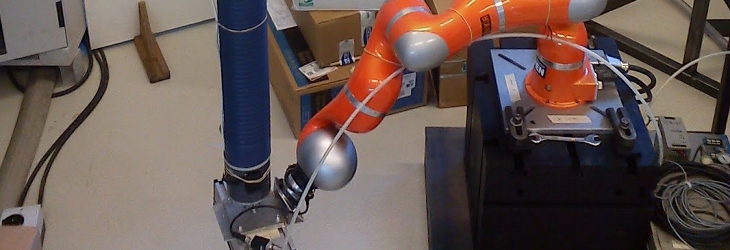
- Commissioning and installation of the experiment equipment: industrial robot KUKA KR 16, KUKA Robot Sensor Interface and the Schunk Force-Torque Sensor
Several scenarios are described for difference handling tasks and branches. We have derived different cell setups from these scenarios (e.g. mounting place, number of passive arms and joints). The single kinematic tests will be performed with experiment formulas based on the user scenarios.
The technical drawings of the robot cell layout and the passive kinematic setup is the current output of task 2. The next steps are the realisation of the passive kinematic modules and the mounting on the robot cell.
The industrial robot could be installed at the facilities of the Fraunhofer IFF in Magdeburg. The KUKA Robot Sensor Interface (RSI) was installed at the robot controller and tested. The robot will be further equipped with the Force-Torque-Sensor via the RSI connection to compensate faulty gripping. A welding and clamping table is a part of the robot cell for mounting the passive kinematics and to perform different handling tasks.