
Aug 3, 2012 , by
Public Summary Month 8/2012
In the final phase of the experiment, objectives of the research were compiled in a final demonstration and in addition, the concept of using the fabrication unit as a digital workbench that is able to accomplish various necessary tasks in a fabrication sequence was introduced in order to show that the unit was able to react on the changing conditions a “workspace”, the building site.
After handling each task in the sequence separately, they were all put together in a single fabrication chain that consisted of: (1) Measurement of the inclination of a workspace and orienting the work tool (gripper) accordingly by transferring the angle data to the robot controller, (2) scanning the workspace (inclined frame) and importing it as 2D-lines to the design software (3) adapting the algorithmic design of a wall structure to be built in that workspace according to the scanned and recognized changes in the dimensions, inclination, etc., and (4) robotically cutting and placing adapted and custom shaped building elements of this algorithmically designed wall structure.
Jun 10, 2012 , by
Public Summary Month 6/2012
Regarding the preparations of the fourth (final) demonstrator, these two months, mainly the focus was to handle the scanning of the steel frame (which is going to be the workspace in the demonstrator), finding the right orientation of the gripper regarding the inclination on the workspace and the cutting tasks separately. All these tasks were successfully accomplished with small mock up demos, and prepared to be put together in the main (fourth) demonstrator in the following weeks. In addition to involving all 3 of the experiment objectives; in this fourth demonstrator, the intention is to use the robotic unit as a digital workbench as if on a construction site.
Apr 5, 2012 , by
Public Summary Month 4/2012
Following the pioneering demonstration in late January 2012, in which a modular 8-meter wall was assembled in 1:1 scale by 13 consecutive self-positioning of the mobile fabrication unit in an unknown environment (the parking space of ETH Zurich), this month, mainly the focus was to document and publish the progress achieved so far, in addition to the preparations done for the fourth demonstration. Next demonstration will involve all 3 of the objectives; being mobility, man-machine interaction and handling of material tolerances; also with the intention being to alter the local reference system into a global one in several terms. Also, the main progress involving Task 3 is concluded, still, this progress will be used in the 4th demonstrator.
Feb 20, 2012 , by
Public Summary Month 2/2012
Complementing to the prior experimentations in previous months on man-machine interaction and handling of material tolerances, current stage of the project focuses on the proof of the concept of mobility.
A system is developed for self-positioning of the mobile unit through the 3D scanning of a local reference. In the demonstration, an 8-meter long modular wall is assembled by 13 consecutive self-positioning of the mobile fabrication unit in an unknown environment (Fig 1). Next stage of the project involves an integration of the 3 objectives; being mobility, man-machine interaction and handling of material tolerances.
The demonstration that took place in the last month was the pioneering experimentation on putting the mobile fabrication unit in its context – on the construction site. The context is chosen as the parking space of ETH Zurich with a ceiling height of 2.50 m. It is the pioneering demonstration for building a large building element on-site.
Initial Tests on Relocation (proof of concept with 3 consecutive moves)
Prior to the fabrication of the fragile structure (the wall) in the parking space, a small scale demonstration took place for proving the concept of mobility according to a local reference system.
In this system, the 3D scanner which was implemented on the robot is used to self-position the mobile unit. The scanning mechanism finds the center point of the metal disk and this point is set as the origin of the plane (coordinate system) that is defined in the CAD model for each new position.
Real-World Conditions
The data from the CAD model of the structure is imported to the robot controller using the system developed on the software side. The wall, the fragile structure, is designed and partitioned according to the simulation studies done with offline programming for finding out the most feasible positioning of the fabrication unit.
The whole design complexity of the structure arises from the superposition of algorithmic rules with cannot be applied easily in a manual fabrication process. Several aspects of the design is driven by the robotic fabrication method chosen.
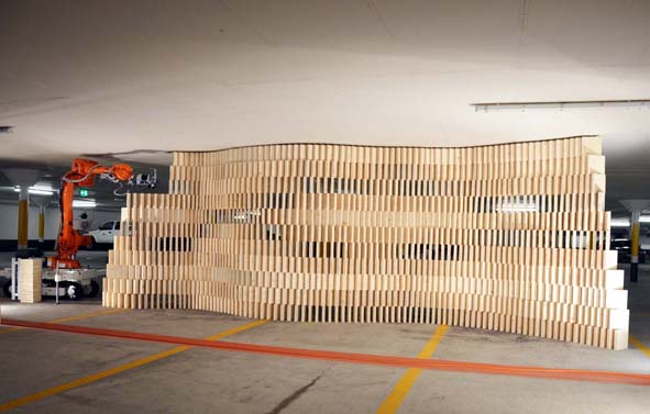
Fig. 1: The fragile structure: A modular, robotically fabricated 8-meter long wall.
Dec 5, 2011 , by
Public Summary Month 12/2011
The tests and framework studies that have been done in the last two months, belong partially to Task 2 (Positioning/Relocation), partially to Task 3 (Site Tolerance) and partially to Task 4 (Material Tolerances). Current stage of the project requires an integral progress on all of these 3 tasks and it aims proving the steps of the hypothesis developed for the final demonstration. Based on the theoretical study/literature survey on robots in construction sites two hypothetical scenarios were developed for two different cases, and a hypothetical framework (Fig 1) was set for these two scenarios. Both of the scenarios involve building a modular wall with the robot on the construction site either with reference to existing elements in the workspace or in an undefined workspace.
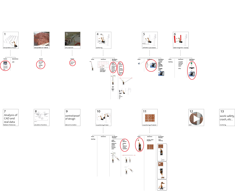
Fig. 1: Hypothetical framework set for the two scenarios developed
Setting a hypothetical framework clarified all the steps to be taken from start to end for the developed scenarios. Depending on the scenario chosen, hardware, method of data handling, utility and controlling mechanism changes.
Description of the Hypothetical Framework
As it can be seen in Fig 1, framework consists of the following stages:
- Transportation of robot to construction site,
- Transportation of material to construction site,
- Preparing the set-up (power),
- Positioning
- Calibration (3-point calibration)
- Object recognition / measuring
- Feedback of tolerances
- Calculation of solutions
- Data communication
- Re-positioning of robot
- Re-positioning of material
- Starting to build
- Monitoring
Tests on Self-Orientation
In this test, 3D scanner is programmed to measure 3 taught points from the tilted wooden board and by drawing a plane through these points, it finds the right orientation for the gripper.
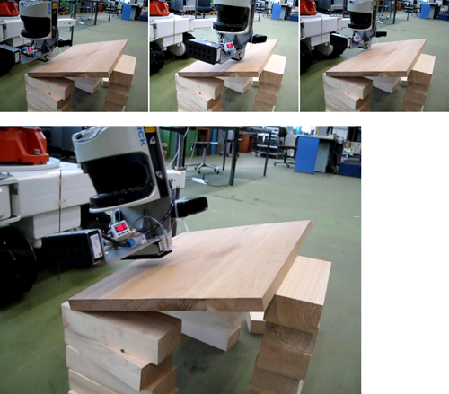
Fig. 2: 3D scanner is programmed to measure 3 taught points from the tilted wooden board and by drawing a plane through these points, it finds the right orientation for the gripper
Tests on Self-Positioning
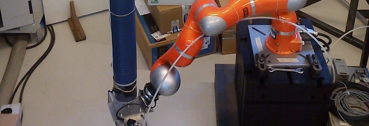
The 3D scanner which was implemented on the robot was also used to test self-positioning with the help of a metal disk whose central point was used as a reference marker (satellite). With the satellite, robot will be able to move several times, re-positioning itself according to the measured coordinates of the center point of the satellite.

Fig. 3: A 3D scanner attached to the gripper of the robot finds/measures the center point of the steel disk (satellite) and gripper moves to that measured point accordingly
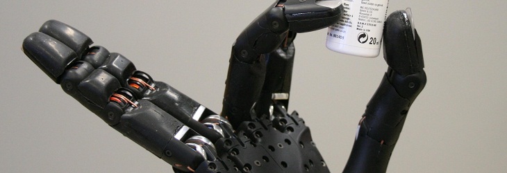
Tests on Material Gripping
Tests done on material gripping cover trying out the material size that is being planned to be used in the final demonstration, and building a material dispenser out of aluminum profiles integrated to the robot. This material dispenser is adaptable to different material sizes and attached to the robot.