
Jan 3, 2013 , by
Public Summary Month 11/2012
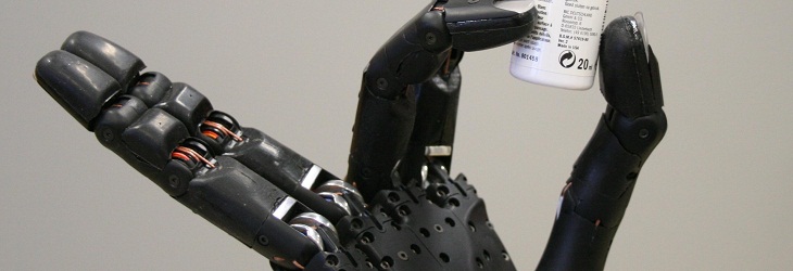
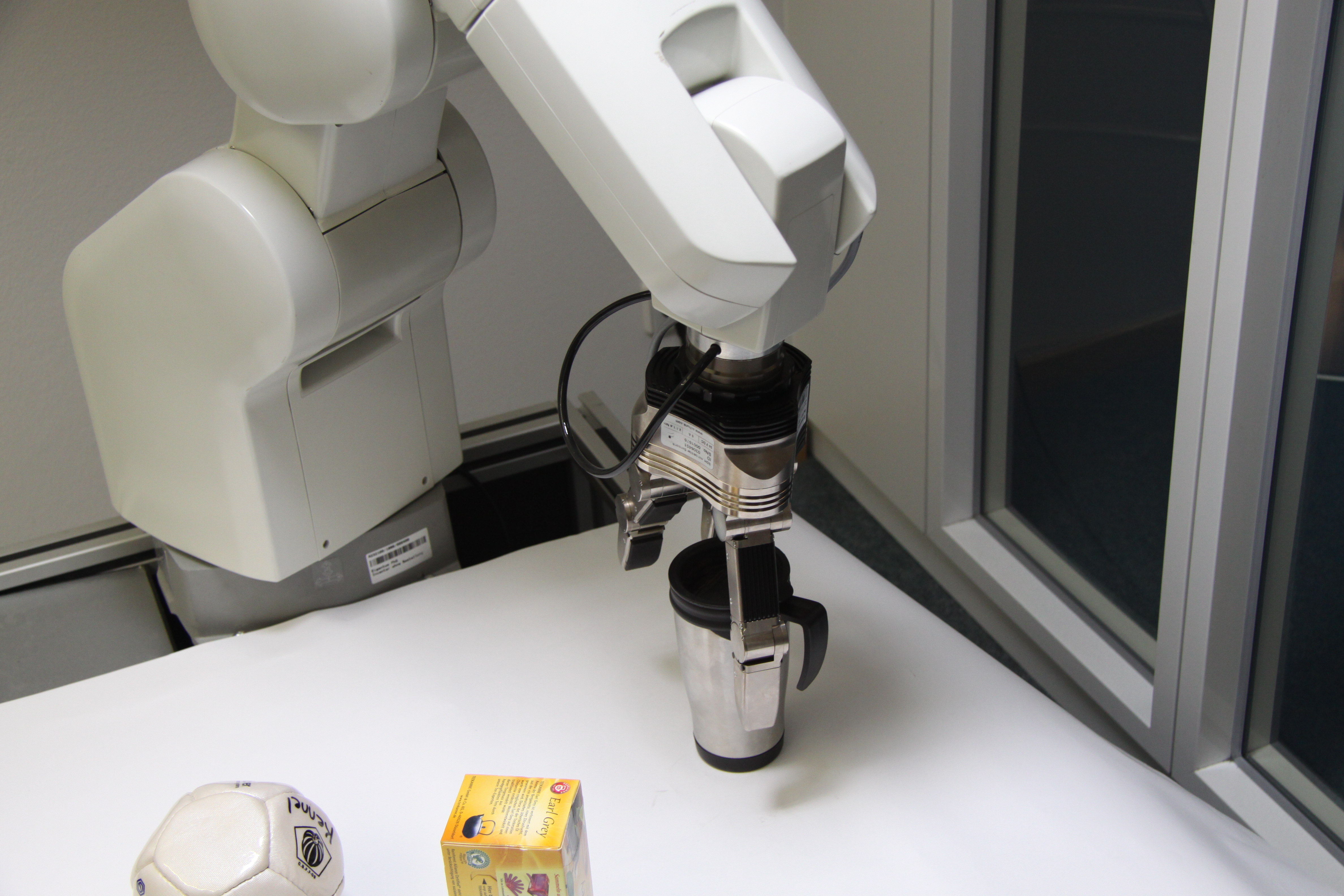
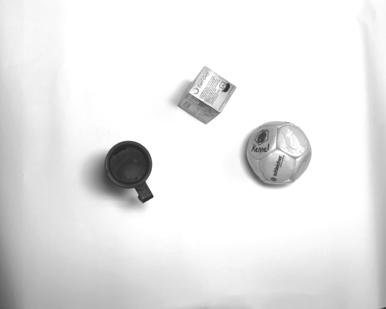
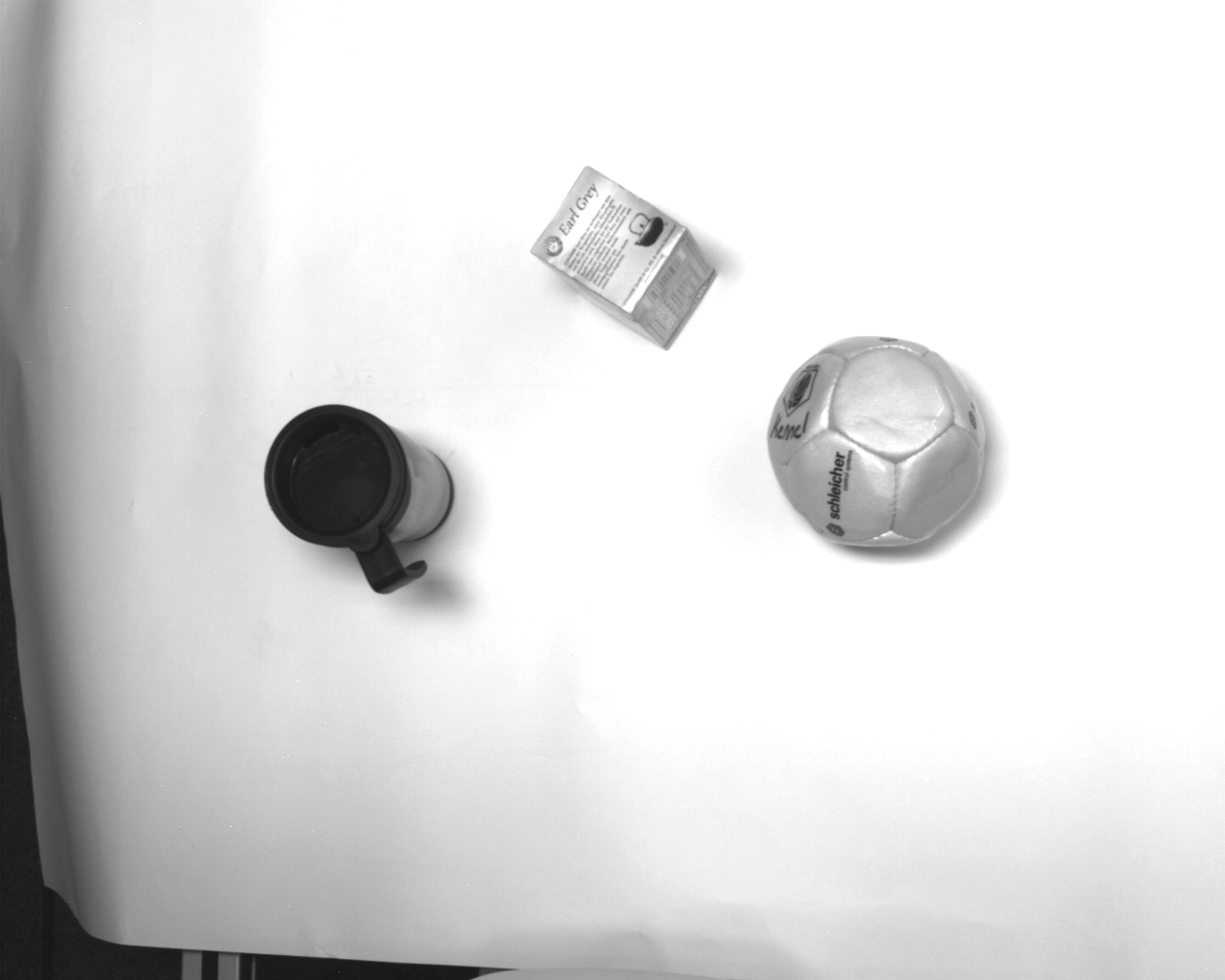
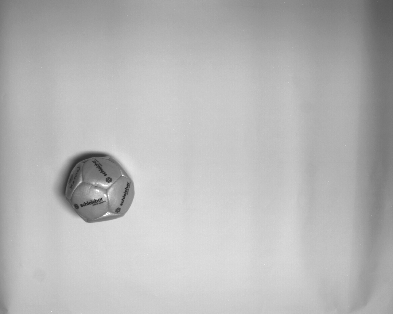
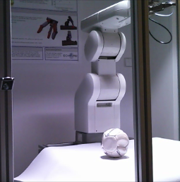
We tested our system with a couple of natural objects (telephone headset, cup, tea box, and ball) which are more or less good-natured but which can neither be called artificial nor simplified. Although there are big gaps in the surface reconstruction no problematic artifacts could be observed that prevented the successful grasp of the tested objects when the object was standing upright.
In our experiment BRACOG we could successfully show that it is possible to initiate grasps only by voluntary modulation of brain waves. We conclude that we finished the experiment successfully.
Oct 18, 2012 , by
Public Summary Month 9/2012
We started to implement an automated error correction. The detection of an error we aim to decode from brain signals that are evoked after an unexpected feedback.
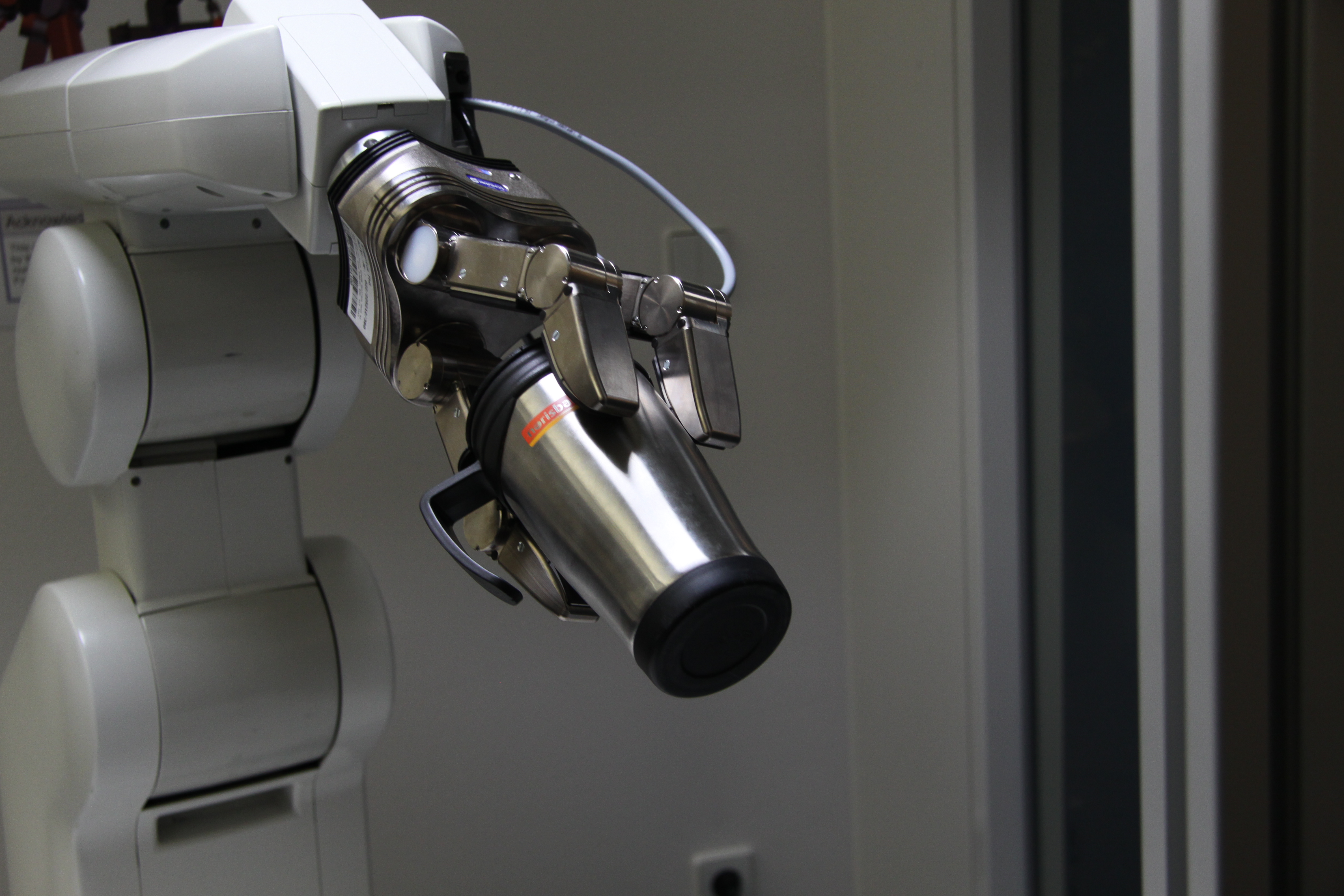
We succeeded to complete the steps from object recognition to a successful grasp of the robotic gripper. In the following we present the underlying tool-chain.
The scene scan consists of recording two stereoscopic images. We extract point clouds that circumscribe the objects.
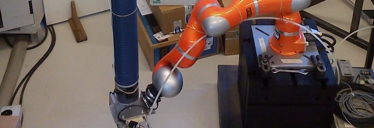
The grasp-planner iteratively moves the robot in the force-field.
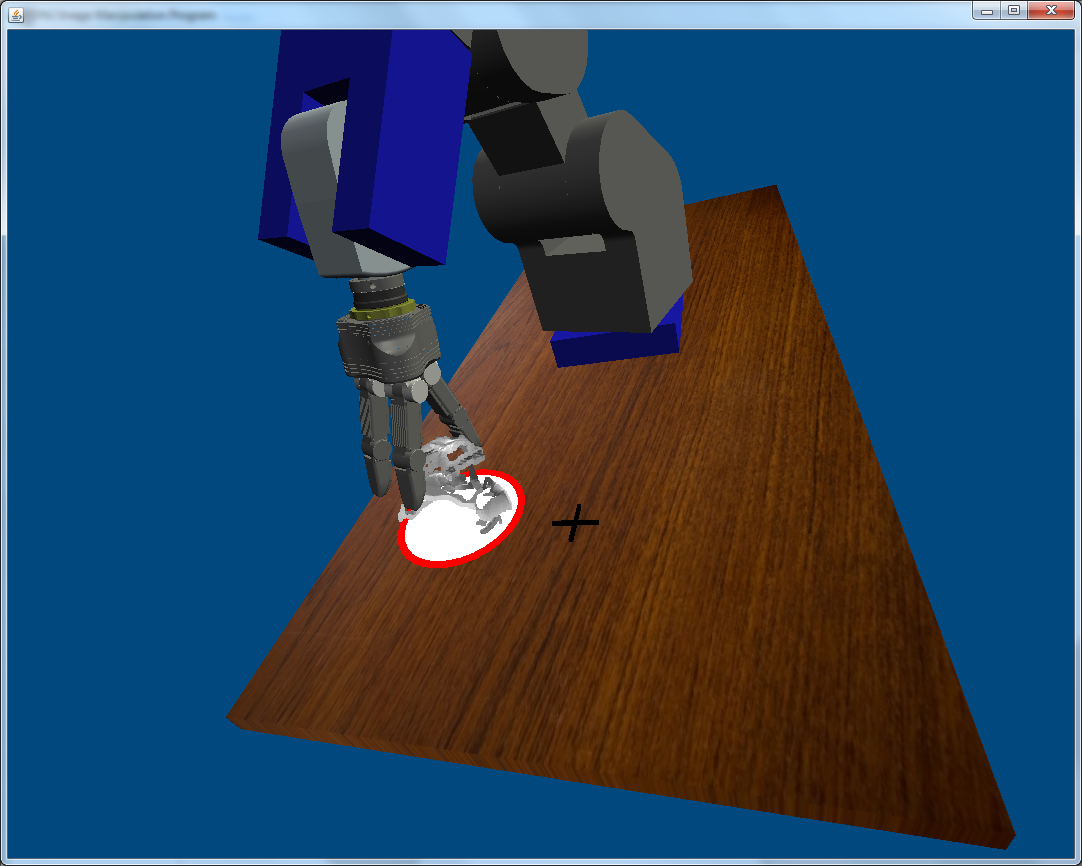
The robot is moved synchronously with its virtual model.


Aug 3, 2012 , by
Public Summary Month 7/2012
TASK 3 + TASK 4:
We finished the verification of object selection paradigms for grasp initiation. The P300 and SSVEP paradigms differ in the number of alternatives as well as trial durations, but reveal comparable detection rates and information transfer rates (bit/min, see Figure 1). We prefer the P300 over the SSVEP paradigm for object selection for three reasons: the feasibility of gaze independence, the flexibility regarding the number of selectable objects and the more convenient task experience of subjects.
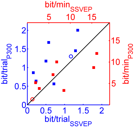
Figure 1: Direct comparison of bit-rates between SSVEP as well as the P300 experiment (each square one subject). Blue data points are scaling in bit/trial, red data points in bit/min. Circles represent averages over subjects.
TASK 9:
After calibration, matching pixels in the left and right camera pictures can be used to calculate their spatial depth. To this end, all resulting 3D points are defined in the camera coordinate system. The transformation to robot coordinates is calculated by using calibration markers in the robot framework. Furthermore, we finished the image-based segmentation algorithm.
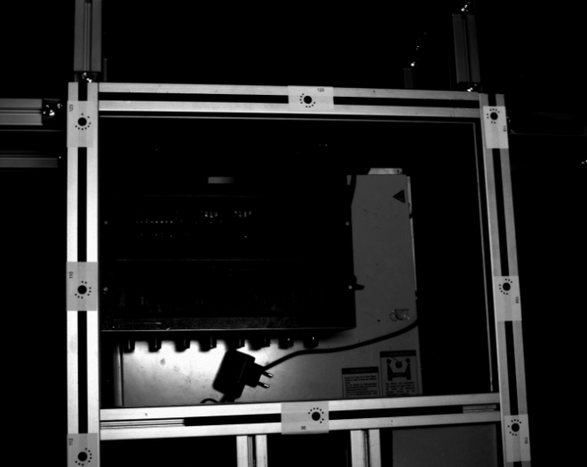
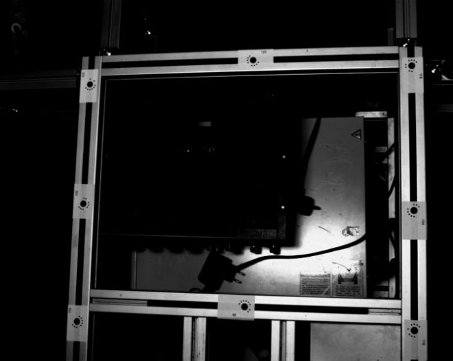
Figure 3: Markers on the robot framework
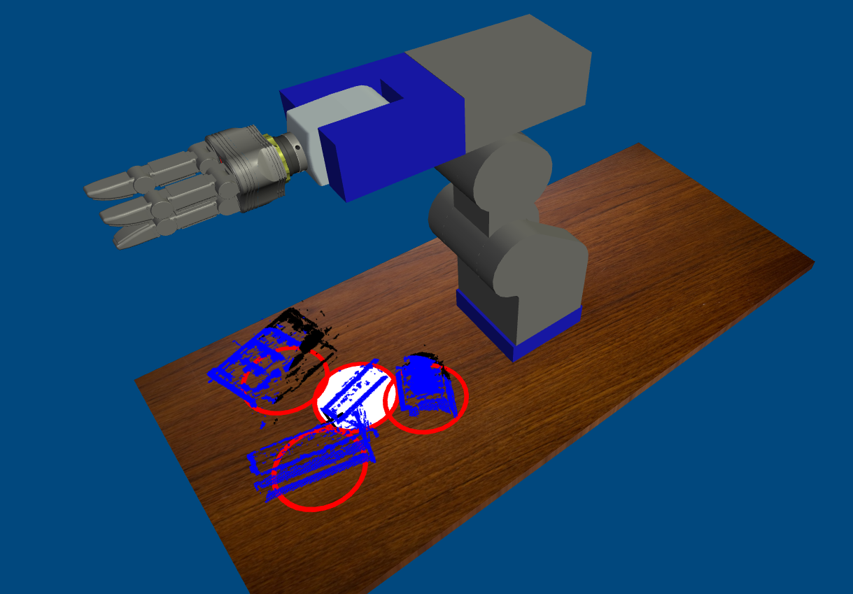
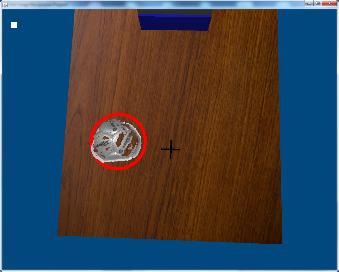
Figure 4: Recognized grasp targets
In order to deal with artifacts, we added an algorithm to analyze the neighborhood of each 3D-point. Figure 5 shows the result of the algorithm.
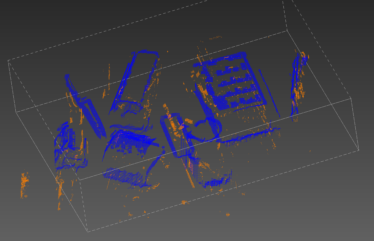
Figure 5: Overlay of original and artifact-cleansed scene. Orange points are identified as artifacts and deleted.
TASK 10:
We realized a need to fine-tune our strategy to deal with huge holes in the grasp targets resulting from object recognition. Our current strategy is to put the point-poles used for the force-based grasp planning on a bounding ellipsoid containing the object (see Figure 6).
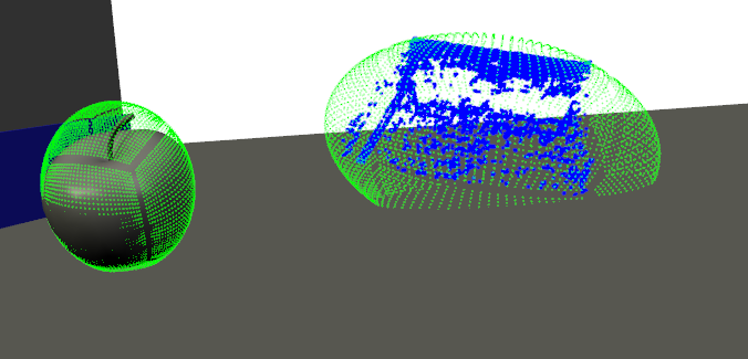
Figure 6: Distributed point-charges for force-based grasp planning of 3D-recognized objects
Jun 22, 2012 , by
Public Summary Month 5/2012
TASK 3:
We further investigated the motor imagery (MI) paradigm in more detail by evaluating the ability of 17 subjects to control the grasp initiation of a virtual arm. Our results indicate that good MI control in our BCI critically depends on the presence of µ‑rhythms Subjects who did not exhibit the rhythm could not achieve control.
We now extended the object selection paradigm such that a virtual robot performs a grasp of the object as feedback rather than displaying colored rings. Moreover, we successfully tested the system with the real robot moving simultaneously with the virtual robot.
TASK 4:
We improved our P300 based object selection setup. Specifically, we increased the number of selectable objects to six. The current paradigm also will serve to derive error signals from brain activity when erroneous feedback was provided.
TASK 9:
We realized that lighting conditions are critical for optimal stereo object recognition.
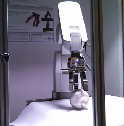
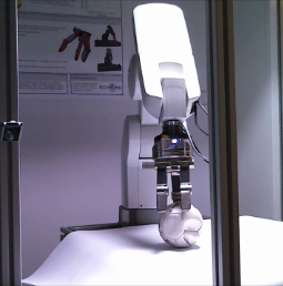
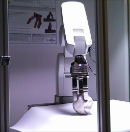
Therefore, we extended our setup by a dimmable light source (see Figure 1 and Figure 2 )
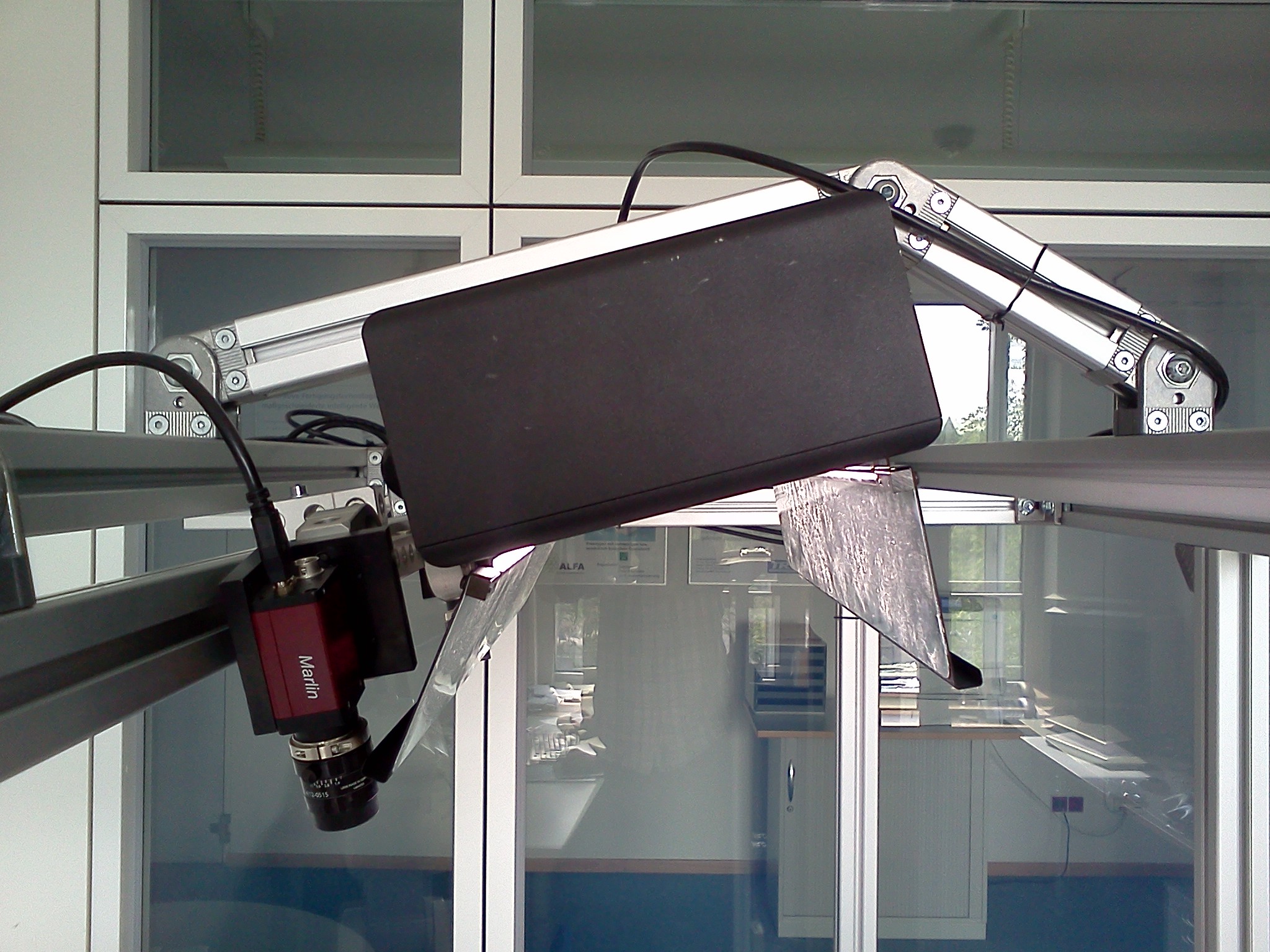
Figure 1: Object recognition system. The new system consists of two grayscale cameras and a dimmable lamp (2x55W).
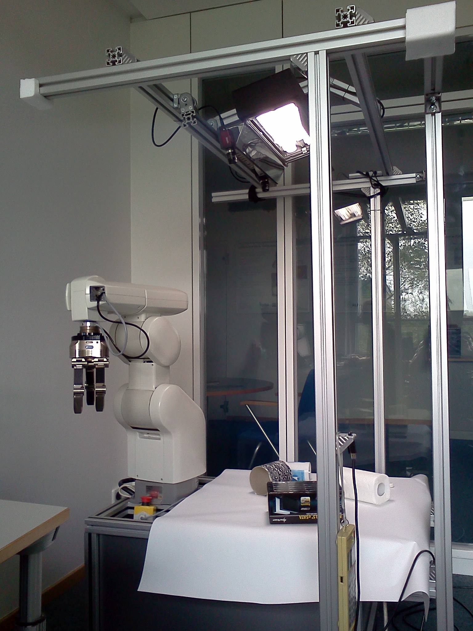
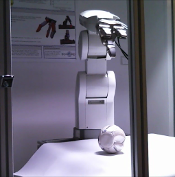
Figure 2: Current demonstrator setup
With improved image quality we succeeded in scanning different objects placed on the table in front of the robot (see Figure 3 and Figure 4).
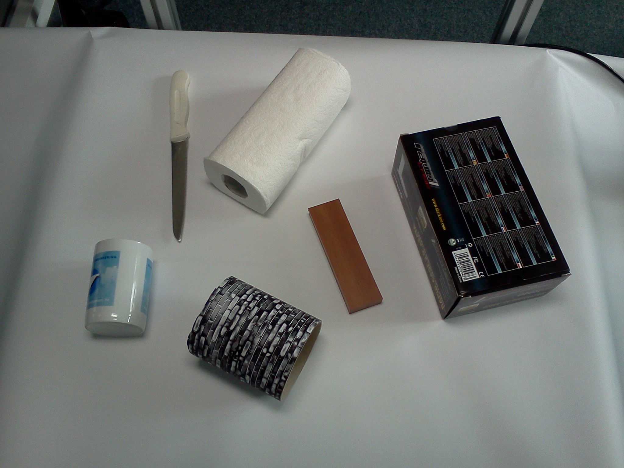
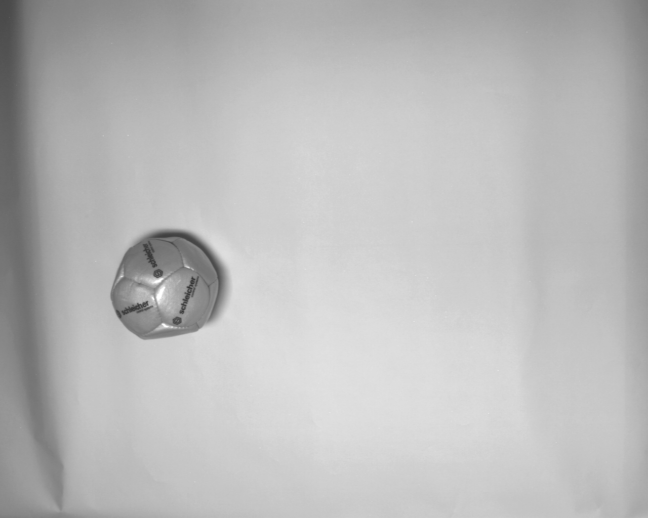
Figure 3: Different test objects for optical recognition
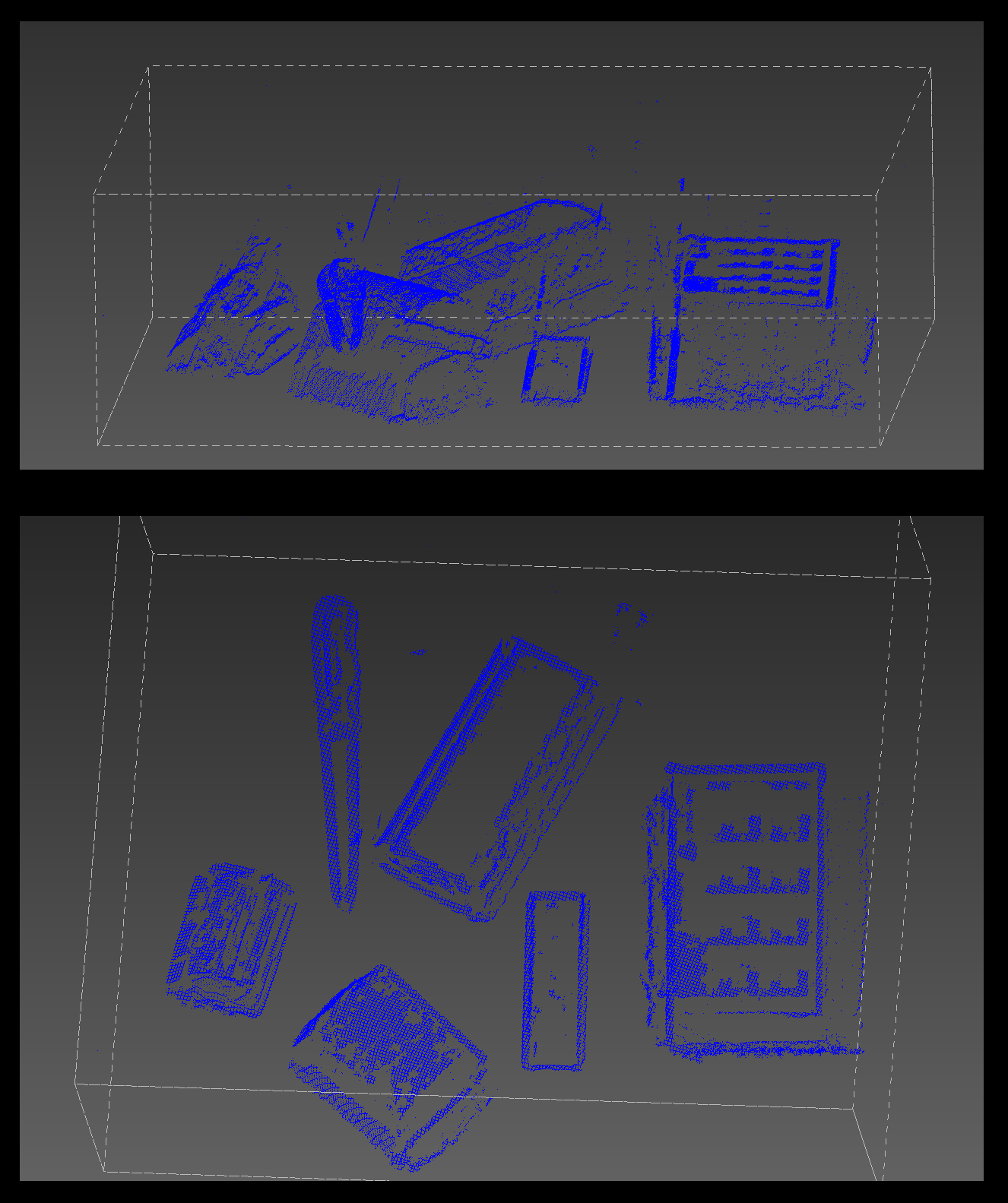
Figure 4: Point clouds obtained from the 3D object recognition system with improved illumination
TASK 11:
We submitted a multimedia report draft to ECHORD which is now embedded in our websites.
Apr 13, 2012 , by
Public Summary Month 3/2012
TASK 3:
We finished the test of the first version of the SSVEP based object selection task with 19 participants. The maximum recognition rate was 91.7% (guessing level 25%). So far the SSVEP-paradigm provided the best results among the tested algorithms.
TASK 4:
We found a significant improvement to using the object’s flicker frequency alone when we included the 1st and 2 nd harmonic of the flicker frequency. No further improvement was found with different approaches of preprocessing, noise cancellation, frequency decomposition, channel selection and different classifier algorithms.
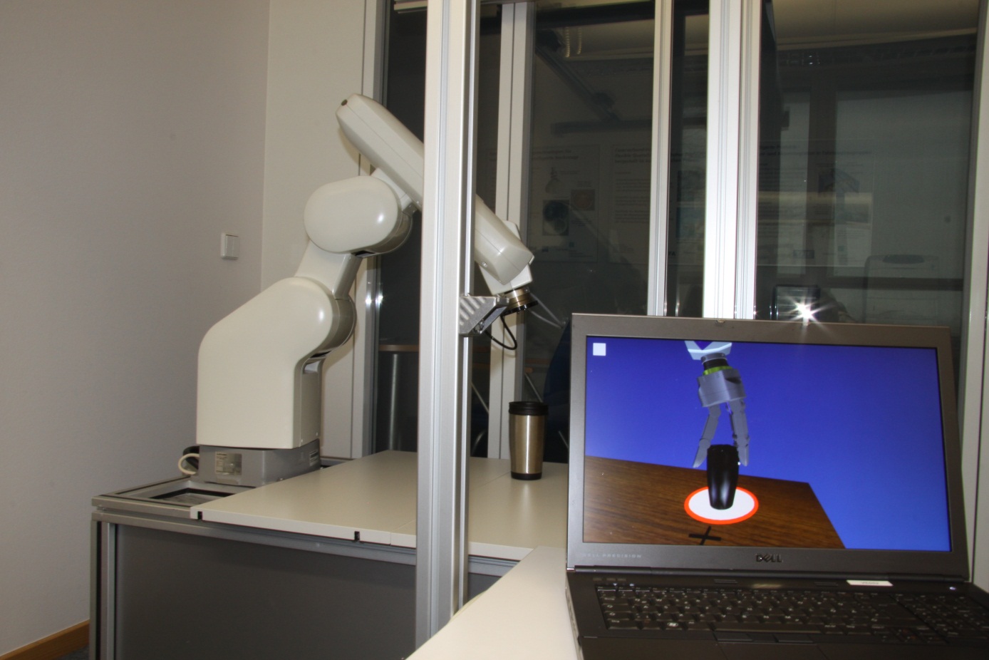
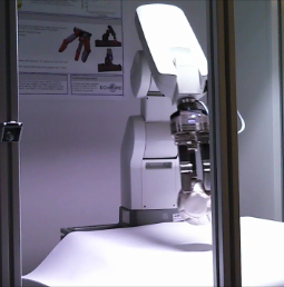
Figure 1: Demonstrator and virtual model
TASK 9:
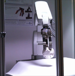
A stereo-vision based object-recognition-system brings along a major additional complication compared to geometry imported from a 3D modeler: Only parts of the object surface visible to the cameras can be recognized. We realized during the experiment, the robot has a quite limited workspace. Consequently, an eye-in-hand-setup in fact makes no sense: Therefore we constructed a mechanical carrier holding the cameras in one specific position (see Figure 2).
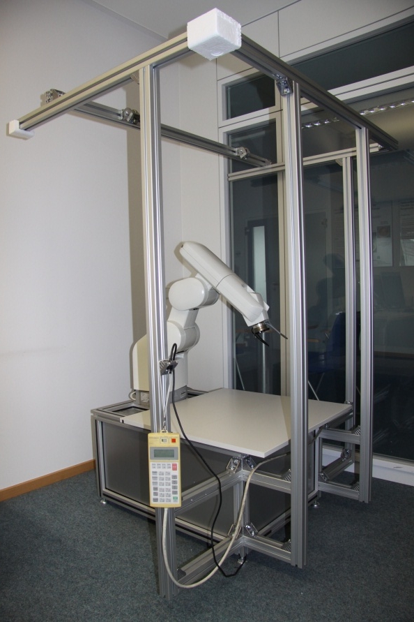
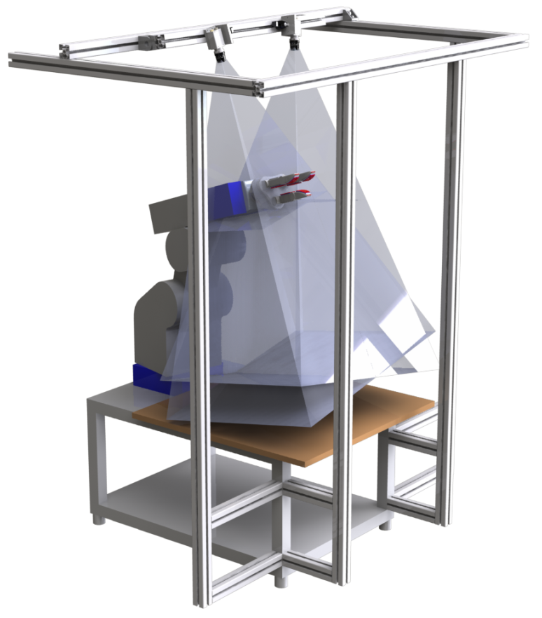
Figure 2: Current demonstator setup
TASK 11:
We finished the implementation of the new RESI communication methods. Now we can couple the robot with the MEG system over the Internet.